I thought I’d begin my first blog post talking a little bit about OS development, but more specifically CPU inner workings.
IRQs
IRQs, or interrupt requests, are sent by the CPU to the IO/APIC. The IO/APIC (which I’ll cover later), translates the IRQ into an interrupt vector which is used to index into IDT (shown later). signal whatever code is running to stop and call an ISR (Interrupt Service Routine)
These IRQs can be a multitude of things, but there are a few constants. In an x86 system, here are some of the common IRQ lines being used (source: http://liujunming.top/2023/08/12/Notes-about-Interrupt-Request-Lines-IRQs/)
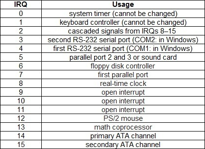
These are of course, mostly present in old systems (as denoted by the 2 RS-232 serial ports and floppy disk controller). However, things like the system timer and keyboard controller are constant.
The IDT (Interrupt Descriptor Table)
The IDT is what connects interrupt vectors to their respective ISRs (Interrupt Service Routines). The OS usually initializes it like so:
First, initialize the pointer to the IDT table. This is done using a structure, defined below as idtPtr_t
typedef struct {
    uint16_t baseLow; // Lower 16 bits (0-15) of the interrupt routine address (address to jump when interrupt fires.)
    uint16_t segmentSelector; // Code segment selector in GDT
    uint8_t reserved; // Reserved. Should be 0.
    uint8_t flags; // Bit flags.
    uint16_t baseHigh; // Higher 16 bits (16-31) of the interrupt routine address (see baseLow)
} __attribute__((packed)) idtEntry_t;

typedef struct {
    uint16_t limit; // size of the IDT
    uint32_t base_addr; // base address of the IDT
} __attribute__((packed)) idtPtr_t;
After this, the Programmable Interrupt Controller (or PIC) is initialized, like so (it’s supposed to be cleaner but this is what I wrote for now):
outportb(0x20, 0x11);
outportb(0xA0, 0x11);
outportb(0x21, 0x20);
outportb(0xA1, 0x28);
outportb(0x21, 0x04);
outportb(0xA1, 0x02);
outportb(0x21, 0x01);
outportb(0xA1, 0x01);
outportb(0x21, 0x0);
outportb(0xA1, 0x0);
I don’t have much experience with the PIC so I’m not entirely able to explain what this code does right now. For cleaner code, please see pic.c in my reduceOS repo (even though it’s not currently, as of Apr 8 2024, being used).
After that, the ISR handlers are installed.
Finally, the IDT itself is installed, using the lidt assembly instruction.
IO/APIC
The Intel I/O Advanced Programmable Interrupt Controller is a chip used to distribute interrupts in a more complex manner than the standard, boring 8259 PIC chip as shown in the IDT section.
This chip is much more complex to initialize, as it can only be detected through ACPI (Advanced Configuration Power Interface) tables (or more specifically the MADT). Entry identification 0x02 tables within those MP tables are for the I/O APIC, and there can be multiple per system.
Each IO/APIC has a few different parameters:
- APIC ID
- Base MMIO address
- First IRQ (or GSI, global system interrupt)
So, you can have something like 2 IO/APICs, one handling IRQs 0-23 and the other handling IRQs 24-47.
I won’t use any code examples since my I/O APIC code is still in development, along with my ACPI code (I’ll have another blog post on that later).
ISRs
Honestly, these are the simplest. Interrupt Service Routines, or ISRs, are used as certain call handlers to specific interrupts. For example, one ISR handler could be a keyboard driver, or another could be a PIT (Programmable Interval Timer) driver.
ISRs are usually called by another function within the kernel (for me, it’s isrIRQHandler and isrExceptionHandler), which call functions that register themselves as interrupt handlers.
You can have a further look at my code in isr.c on my reduceOS repo.
And that’s all!
Thanks for reading! Sorry if it’s complex :/